Deploy ERSPAN with an ExtraHop sensor and Brocade 5600 vRouter in AWS
This guide explains how to install and configure an example environment within Amazon Web Services (AWS) through built‐in ERSPAN capabilities on the ExtraHop sensor and the Brocade 5600 vRouter.
Encapsulated Remote Switched Port Analyzer (ERSPAN) enables you to monitor traffic on multiple network interfaces or VLANs and send the monitored traffic to one or more destinations, including ExtraHop sensors. Configuring ERSPAN on the Brocade 5600 vRouter with the ExtraHop sensor enables additional mission-critical traffic analytics, monitoring, and visibility across AWS and other cloud platforms.
Additional references
The document assumes a certain level of familiarity with networking. Completing the steps in this guide requires an AWS account. If you are new to ExtraHop, Brocade, or Amazon Web Services, see the following links for additional information:
- Deploy the ExtraHop sensor in AWS
- Using the Brocade 5600 vRouter 5600 in AWS
Configure an AWS Virtual Private Cloud network
In this section, you will configure a new virtual private cloud (VPC), an Internet gateway, subnets, and routing services.
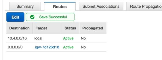
Set routes
Before traffic is allowed in or out of the new VPC, routing and traffic security rules must be configured. By default, all outbound traffic is allowed, but inbound traffic is more restrictive.
-
Click Save.
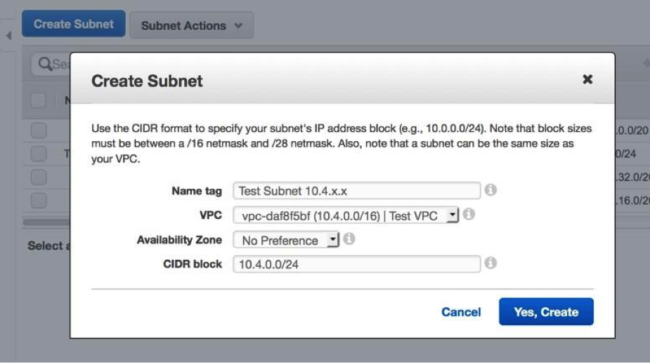
Create a subnet
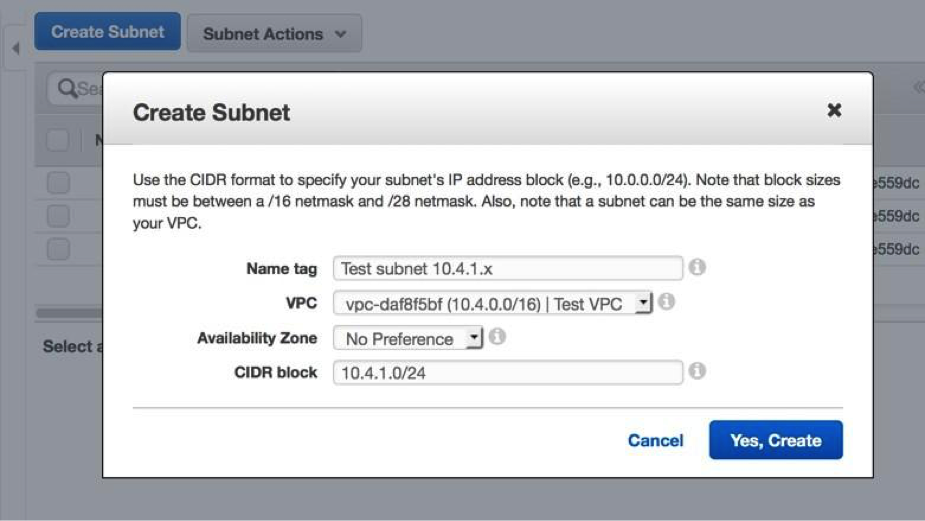
This example network has a public and private subnet within the CIDR block you configured earlier. You will configure 10.4.0.0/24 as the public subnet and 10.4.1.0/24 as the private subnet.
-
Click Yes, Create.
-
Repeat steps 1-6 to create a private subnet with the
10.4.1.0/24 CIDR block.
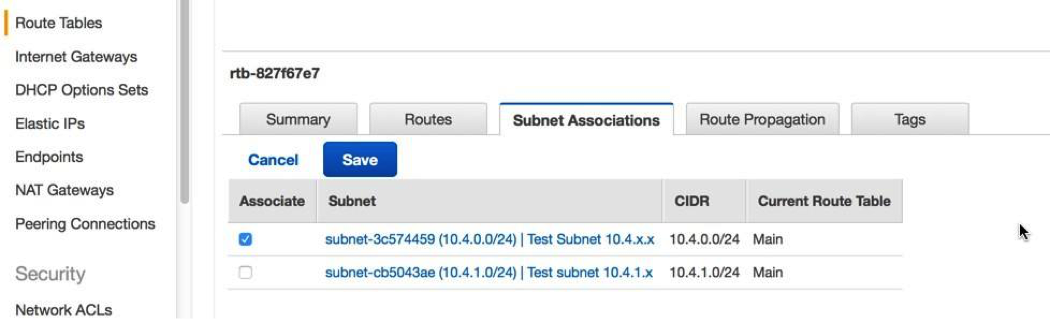
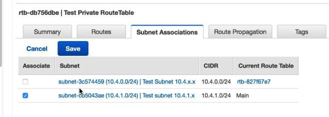
Associate the route table with the subnet
-
Click Edit and select the public subnet of
10.4.0.0/24, and then click
Save.
-
Click Edit and select the private subnet
10.4.1.0/24 and then click Save.
Make note of this route table, in a subsequent step an association is made to the private interface of the Brocade vRouter with a route.
Add inbound rules to the security group
-
Click Save.
Note: This is a non-production configuration; you would not typically allow all IP addresses to access your instance. 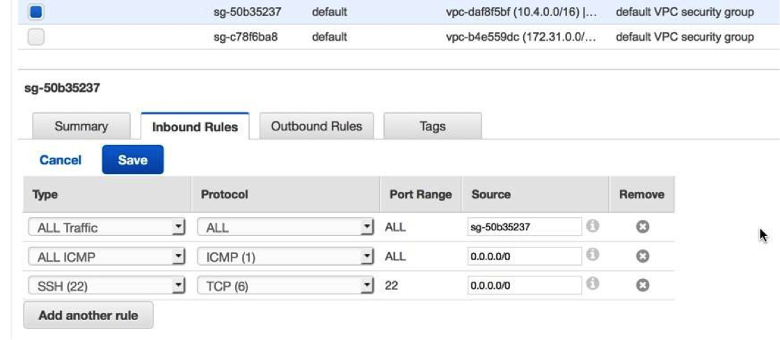
Summary
In this section you created a virtual public cloud, a private subnet for the 10.4.1.0/24 network and a public subnet for the 10.4.0.0/24 network. In addition, you created routing tables for routing traffic within the VPC subnets and externally through an Internet Gateway. Security groups allow traffic in or out of the VPC and you configured inbound rules to allow ICMP and SSH traffic.
Configure the Brocade 5600v router
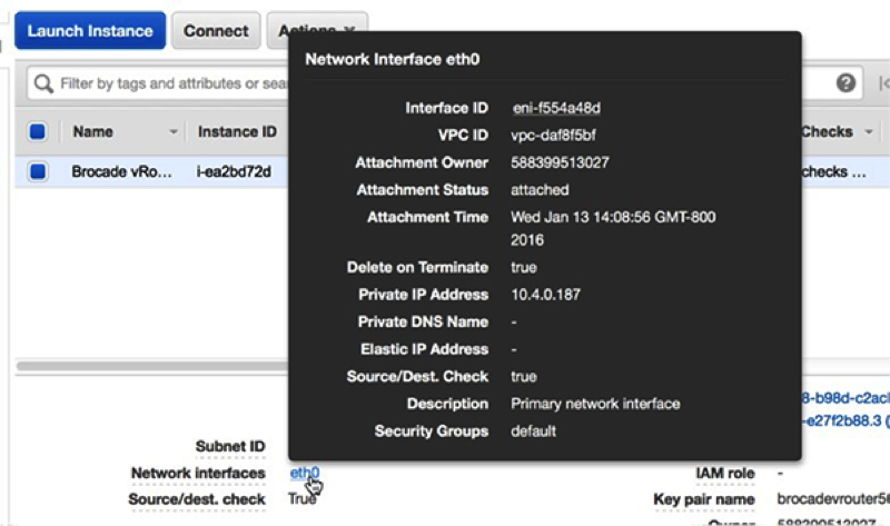
In this section you will configure a new Brocade 5600v router within the public subnet created previously, and assign an Elastic IP to configure and test the setup through SSH.
-
Click the link associated with the Interface ID. In this
example, the ID is eni-f554a48d.
(Optional) Configure Linux client for traffic generation
In this section and the next, you will configure a new Linux AMI in order to verify the Brocade vRouter and ExtraHop Discover configuration. If other sources of traffic are available, then these sections can be skipped.
| Note: | A Linux client is selected in the following example. |
- Click the Console Home icon in the upper left corner to return to the AWS Management Console page.
- In the Compute section, click EC2.
- In the navigation pane, click Instances.
- Click Launch Instance to start the Amazon Machine Image (AMI) wizard.
- Locate an Ubuntu Server image in the list and then click Select.
- Select the t2.micro instance type and then click Next: Configure Instance Details.
-
On the Configure Instance Details page, complete the
following steps:
- Click Next: Add Storage. No changes are necessary.
- Click Next: Tag Instance. No changes are necessary.
- Click Next: Configure Security Group.
-
On the Configure Security Group page, complete the
following steps:
Configure an ExtraHop EDA 1000v
In this section, you will configure a new ExtraHop EDA 1000v sensor.
Configure NAT on the vRouter to access the ExtraHop system
To access the ExtraHop system, NAT must be configured on the vRouter.
(Optional) Create a new volume for packet capture storage
Create a new volume for the EDA 1000v to store trigger-enabled packet capture data.
- In the navigation pane in AWS, click Volumes.
- Click Create Volume. In the Create Volume dialog box, make sure that the Availability Zone selected is the same zone as the Discover instance and then click Create.
- Select the new volume in the Volumes list and then select Attach Volume from the Actions drop-down menu. In the Instance field, select your Discover instance and then click Attach.
- In the navigation pane, click Instances.
- Select the Discover instance in the list and then click .
- When the Discover instance returns to a running state, log in to the Administration settings on the ExtraHop system through https://<extrahop-hostname-or-IP-address>/admin.
- In the Appliance Settings section, click Disks and verify that the new packet capture disk appears in the list of direct connected disks.
- Click Enable on the Packet Capture disk to enable.
Configure ERSPAN and portmonitoring on the Brocade vRouter
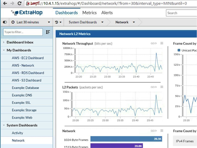
In this section you will configure the ERSPAN and portmonitoring features on the Brocade vRouter to send ERSPAN traffic to the ExtraHop sensor.
-
Log in to the ExtraHop system through
https://<elastic_public_ip:8443>/extrahop and verify
that the ExtraHop is receiving ERSPAN traffic from the vRouter from the Dashboards interface.
Sample Brocade vRouter configuration
vyatta@vyatta:~$ show configuration
interfaces {
dataplane dp0s0 {
address dhcp
ip {
gratuitous-arp-count 1
rpf-check disable
}
ipv6 {
dup-addr-detect-transmits 1
}
mtu 1500
vlan-protocol 0x8100
}
dataplane dp0s1 {
address 10.4.1.10/24
ip {
gratuitous-arp-count 1
rpf-check disable
}
ipv6 {
dup-addr-detect-transmits 1
}
mtu 1500
vlan-protocol 0x8100
}
erspan erspan1 {
ip {
tos inherit
ttl 255
}
local-ip 10.4.1.10
mtu 1500
remote-ip 10.4.1.15
}
loopback lo
}
protocols {
ecmp {
mode hrw
}
pim {
register-suppression-timer 60
}
pim6 {
register-suppression-timer 60
}
}
security {
firewall {
all-ping enable
broadcast-ping disable
config-trap disable
syn-cookies enable
}
}
service {
nat {
destination {
rule 10 {
destination {
port 445
}
inbound-interface dp0s0
protocol tcp
translation {
address 10.4.1.50
port 22
}
}
rule 20 {
destination {
port 8443
}
inbound-interface dp0s0
protocol tcp
translation {
address 10.4.1.15
port 443
}
}
}
source {
rule 100 {
outbound-interface dp0s0
translation {
address masquerade
}
}
}
}
portmonitor {
session 25 {
destination erspan1
erspan {
header type-II
identifier 200
}
source dp0s1 {
direction both
}
type erspan-source
}
}
ssh {
authentication-retries 3
disable-password-authentication
port 22
timeout 120
}
}
system {
acm {
create-default deny
delete-default deny
enable
exec-default allow
operational-ruleset {
rule 9977 {
action allow
command /show/tech-support/save
group vyattaop
}
rule 9978 {
action deny
command "/show/tech-support/save/*"
group vyattaop
}
rule 9979 {
action allow
command /show/tech-support/save-uncompressed
group vyattaop
}
rule 9980 {
action deny
command "/show/tech-support/save-uncompressed/*"
group vyattaop
}
rule 9981 {
action allow
command /show/tech-support/brief/save
group vyattaop
}
rule 9982 {
action deny
command "/show/tech-support/brief/save/*"
group vyattaop
}
rule 9983 {
action allow
command /show/tech-support/brief/save-uncompressed
group vyattaop
}
rule 9984 {
action deny
command "/show/tech-support/brief/save-uncompressed/*"
group vyattaop
}
rule 9985 {
action allow
command /show/tech-support/brief/
group vyattaop
}
rule 9986 {
action deny
command /show/tech-support/brief
group vyattaop
}
rule 9987 {
action deny
command /show/tech-support
group vyattaop
}
rule 9988 {
action deny
command /show/configuration
group vyattaop
}
rule 9989 {
action allow
command "/clear/*"
group vyattaop
}
rule 9990 {
action allow
command "/show/*"
group vyattaop
}
rule 9991 {
action allow
command "/monitor/*"
group vyattaop
}
rule 9992 {
action allow
command "/ping/*"
group vyattaop
}
rule 9993 {
action allow
command "/reset/*"
group vyattaop
}
rule 9994 {
action allow
command "/release/*"
group vyattaop
}
rule 9995 {
action allow
command "/renew/*"
group vyattaop
}
rule 9996 {
action allow
command "/telnet/*"
group vyattaop
}
rule 9997 {
action allow
command "/traceroute/*"
group vyattaop
}
rule 9998 {
action allow
command "/update/*"
group vyattaop
}
rule 9999 {
action deny
command "*"
group vyattaop
}
}
read-default allow
ruleset {
rule 9999 {
action allow
group vyattacfg
operation "*"
path "*"
}
}
update-default deny
}
config-management {
commit-revisions 20
}
console {
device ttyS0 {
speed 9600
}
}
host-name vyatta
login {
session-timeout 0
user vyatta {
authentication {
encrypted-password "********"
public-keys TestBrocade {
key xxx
type ssh-rsa
}
}
level admin
}
}
syslog {
global {
archive {
files 5
size 250
}
facility all {
level warning
}
}
}
time-zone GMT
}
Thank you for your feedback. Can we contact you to ask follow up questions?