Deploy the EDA 10200 sensor

This guide explains how to install the rack-mounted EDA 10200 sensor.

Installation prerequisites

To install the sensor, your environment must meet the following requirements:
Sensor
2U of rack space and electrical connections for 2 x 1100 W power supplies.
Management
One 10/100/1000 BASE-T network port or one 10G BASE-SR port for appliance management.
Monitoring (capture)
High-performance interfaces: One to four network ports for connection to 100 GbE, 40 GbE, 25 GbE, or 10 GbE sources of packet data, depending on the ordered configuration.
Management + monitoring interfaces: One to three network ports for connection to 1 GbE sources of packet data.
Network Access
Ensure that administrators can access the Administration settings on the sensor over TCP port 443.

For more information about the interfaces on the ExtraHop system, see the ExtraHop Hardware FAQ.

Rear panel ports

EDA 10200

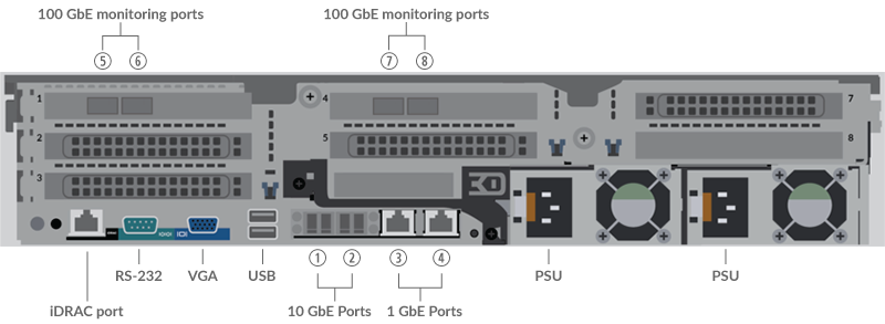
  • One iDRAC interface port
  • One RS-232 serial port to connect a console device
  • One VGA port to connect an external display
  • Two USB 3.0 ports to connect input devices such as a keyboard and mouse
  • Two power ports to connect the appliance to an AC power source
  • Two 10 GbE ports. Ports 1 and 2 can be configured as a management port, management and flow target, or management and RPCAP/ERSPAN/VXLAN/GENEVE target.
    While 10 GbE management + capture interfaces on this sensor can conduct management functions at 10 Gbps speeds, processing traffic such as ERSPAN, VXLAN, and GENEVE is limited to 1 Gbps.
    Tip:In environments with asymmetric routing adjacent to the high-performance interfaces, ping replies might not get back to the sender.
  • Two 10/100/1000 BASE-T network ports. Port 3 is the primary management port. Both ports can be configured as a monitoring port, management port, management and flow target, or management and RPCAP/ERSPAN/VXLAN/GENEVE target.
  • Four 100 GbE-capable ports on two network adapters. These ports are the high-performance monitoring (capture) interfaces.

Supported packet source connectivity

The EDA 10200 can accept packets through ports 1-8. The ports can be connected according to the table below.
EDA 10200 Connector Peer Connector for Packet Source Customer-Supplied Cabling Supported Operating Speeds
Transceiver-based Connectivity
100 GbE QSFP28 SR4 transceiver 100 GbE QSFP28 SR4 transceiver Multi-mode fiber

MPO connectors

100 Gbps, 40 Gbps
40 GbE QSFP+ SR4 transceiver Multi-mode fiber

MPO connectors

40 Gbps
40 GbE QSFP SR BiDi transceiver (Customer-supplied Cisco QSFP-40G-SR-BD only) 40 GbE QSFP+ SR BiDi transceiver Duplex multi-mode fiber LC connectors 40 Gbps
25 GbE SFP28 SR transceiver (with QSFP28-to-SFP28 adapter) 25 GbE SFP28 SR transceiver Multi-mode fiber

LC connectors

25 Gbps, 10 Gbps
10 GbE SFP+ SR transceiver Multi-mode fiber

LC connectors

10 Gbps
Direct Attach Connectivity
Customer-supplied QSFP28 DAC cable, such as the Mellanox MCP1600-Cxxx series 100 Gbps
QSFP28-to-SFP28 adapter with customer-supplied SFP28 DAC cable, such as the Mellanox MCP2M00-Axxx series 25 Gbps
Customer-supplied RJ45 Ethernet cable 1 Gbps 1 Gbps
Note:The packet processing capability of the sensor is 100 Gbps. While it is possible to oversubscribe the sensor by sending more than 100 Gbps of packet data across the four 100 GbE-capable ports, inbound workloads that exceed 100 Gbps will result in dropped packets.

Traffic distribution guidelines

  • Packets from the same flow should be received on the same interface, or on interfaces of the same network interface card (NIC).
  • The ingest on each NIC should not exceed 75% of the rated analysis throughput for the sensor to ensure that traffic is balanced across system resources.
  • If your data feed does not require both interfaces on the NIC, disable the unconfigured interfaces in the Administration settings. For example, configure the sensor with a single interface to ingest 50 Gbps on each NIC. Disable the extraneous ports on each NIC. This configuration optimizes performance for 100 Gbps.
  • A single high-performance ERSPAN target is expected to process 20 to 30 Gbps. On larger sensors, distribute ERSPAN traffic to more interfaces to scale traffic ingest.

Set up the sensor

  1. Rack mount the sensor.
    Install the sensor in your data center with the included rack-mounting kit. The mounting kit supports most four-post racks with either round or square holes.

    Orient the hardware to ensure proper airflow. The cold air intake is through the front of the sensor.

  2. Connect port 3 to your management network.
    The EDA 10200 sensor has two 10/100/1000 BASE-T network ports. With a network patch cable, connect the management port on the sensor to your management network. Port 3 is the default management port on the EDA 10200.
  3. Connect the monitoring port.
    Important:To ensure the best performance for initial device synchronization, connect all sensors to the console and then configure network traffic forwarding to the sensors.
    With the appropriate network cable, connect port 7 on the sensor to a network tap or mirror port on the switch. When configuring multiple monitoring ports, make sure that the transceivers are balanced across adapters. For example, with two transceivers, connect the cable to the transceivers on port 5 and port 7.
    Note:The link lights on the monitoring interface ports do not illuminate until you register the ExtraHop sensor, recordstore, or packetstore with your product key.
  4. (Optional): Connect the iDRAC port.
    To enable remote management of the sensor, connect your management network to the iDRAC port with a network patch cable.
  5. Install the front bezel.
    You must install the front bezel if you want to configure the sensor through the LCD display.

    Insert the USB connector on the right side of the bezel into the USB port on the front of the sensor. Press and hold the release button on the left end of the bezel and push the bezel flush with the sensor until it snaps into place.

  6. Connect the power cords.
    Connect the two supplied power cords to the power supplies on the back of the sensor, and then plug the cords into a power outlet. If the sensor does not power on automatically, press the power button on the front-right of the sensor.

Configure the management IP address

DHCP is enabled by default on the ExtraHop system. When you power on the system, interface 3 attempts to acquire an IP address through DHCP. If successful, the IP address appears on the home screen of the LCD.

If your network does not support DHCP, you can configure a static IP address through the LCD menu on the front panel or through the command-line interface (CLI).

Configure a static IP address through the LCD

Complete the following steps to manually configure an IP address through the front panel LCD controls.
  1. Make sure that the default management interface is connected to the network and the link status is active.
  2. Press the select button (✓) to begin.
  3. Press the down arrow button to select Network, and then press the select button.
  4. Press the down arrow to select Set static IP, and then press the select button.
  5. Press the left or right arrows to select the first digit to change, and then press the up or down arrows to change the digit to the desired number. Repeat this step for each digit you need to change. After you configure the desired IP address, press the select button.
  6. On the Network mask screen, press the left or right arrows to select the first digit to change, and then press the up or down arrows to change the digit to the desired number. Repeat this step for each digit you need to change. After you configure the desired network mask, press the select button.
  7. On the Default gateway screen, press the left or right arrows to select the first digit to change, and then press the up or down arrows to change the digit to the desired number. Repeat this step for each digit you need to change. After you configure the desired default gateway, press the select button.
  8. Confirm your modified network settings on the Settings saved screen, and then press any button to return to the Network Menu.
    Note:Each address is preceded by a letter that identifies whether it is the system IP address (I), the gateway address (G), or the netmask (N).
  9. Press the down arrow and scroll to Set DNS servers, and then press the select button.
  10. Press the left or right arrows on the DNS1 screen to select the first digit to change, and then press the up or down arrows to change the digit to the desired number. Repeat this step for each digit you need to change, and then press the select button to continue to the DNS2 screen.
  11. Configure a second DNS server.
  12. Confirm the DNS settings on the Settings saved screen, and then press any button to return to the Network Menu.
  13. Press the down arrow twice until ← Back appears, and then press the select button.
  14. Press the down arrow twice to select iDRAC. Configure the iDRAC DHCP, IP, mask, gateway, and DNS in the same manner as the IP address.
  15. Press the X button to return to the main menu.

Configure an IP address through the CLI

Complete the following steps to manually configure an IP address from the CLI.

  1. Establish a connection to the ExtraHop system.
  2. At the login prompt, type shell and then press ENTER.
  3. At the password prompt, type the system serial number and then press ENTER.
    The serial number is printed on a label on the back of the sensor. The serial number can also be found on the LCD display on the front of the sensor in the Info section.
  4. Enable privileged commands:
    enable
  5. At the password prompt, type the serial number, and then press ENTER.
  6. Enter configuration mode:
    configure
  7. Enter interface configuration mode:
    interface
  8. Run the ip command and specify the IP address and DNS settings in the following format:
    ip ipaddr <ip_address> <netmask> <gateway> <dns_server>
    For example:
    ip ipaddr 10.10.2.14 255.255.0.0 10.10.1.253 10.10.1.254
  9. Leave configuration mode:
    exit
  10. Save the running configuration file:
    running_config save
  11. Type y and then press ENTER.
    Note:The system updates the running configuration file and applies the new settings when a link is detected on the interface.

(Optional) Configure the 10 GbE management interface

You can configure a 10 GbE port (port 1 or port 2) to manage the system. The commands below move the settings from port 3 to port 1 and then disables port 3. Alternatively, you can configure the 10 GbE management interface in the Administration settings.

  1. Make sure that the port 1 is connected to the 10 GbE network.
  2. Establish an SSH connection to the ExtraHop system.
  3. At the login prompt, type shell and then press ENTER.
  4. At the password prompt, type the system serial number and then press ENTER. The serial number is printed on a label on the back of the sensor. The serial number can also be found on the LCD display on the front of the sensor in the Info section.
  5. Enable privileged commands:
    enable
  6. At the password prompt, type the serial number, and then press ENTER.
  7. Enter configuration mode:
    configure
  8. Enter interface configuration mode:
    interface 1
  9. Move the interface settings:
    Warning:This command overwrites the settings for Interface 1 with the settings from Interface 3. The current settings for Interface 1 will be lost and Interface 3 will be disabled.
    take_settings 3
  10. Type Y to proceed and then press ENTER.

Configure the sensor

After you configure an IP address for the sensor, open a web browser and navigate to the ExtraHop system through the configured IP address. Accept the license agreement and then log in with the setup user account. The password is the system serial number that appears in the Info section of the LCD display and on the label on the back of the sensor. Follow the prompts to enter the product key, change the default setup and shell user account passwords, connect to ExtraHop Cloud Services, and connect to a console.

After the system is licensed, and you have verified that traffic is detected, complete the recommended procedures in the post-deployment checklist.

Last modified 2024-02-05