Deploy the ETA 6150 packetstore
This guide explains how to install the rack-mounted ETA 6150 packetstore.
System requirements
- Packetstore
- 2U of rack space
- 2x750W of power
- Network Access
- TCP ports 80 and 443 must be open.
These ports enable you to administer the packetstore. Requests sent to port 80 are automatically redirected to HTTPS port 443.
| Important: | For maximum performance and compatibility, deploy sensors and packetstores in the same datacenter. |
Rear panel ports
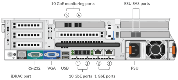
- One iDRAC interface port
- One RS-232 serial port to connect a console device
- One VGA port to connect an external display
- Two USB 3.0 ports to connect input devices such as a keyboard and mouse
- Two 10/100/1000 BASE-T network ports. Port 3 is the primary management port.
- Four 10 GbE ports. Ports 5 and 6 are the monitoring (capture) interfaces.
- Two power ports to connect the packetstore to an AC power source
Configure the management IP address
DHCP is enabled by default on the packetstore. When you power on the packetstore, interface 3 attempts to acquire an IP address through DHCP. If successful, the IP address appears on the home screen of the LCD. If an IP address has not been configured, the LCD displays No IP.
If your network does not support DHCP, you can configure a static IP address through the LCD menu on the front panel or through the command-line interface (CLI).
Configure a static IP address through the front panel
Complete the following steps to manually configure an IP address through the front panel LCD controls.
- Make sure that the default management interface is connected to the network and the link status is active.
- Press the select button (✓) to begin.
- Press the right arrow (>) button to select Net and then press the select button.
- Press the right arrow button twice to highlight DHCP and then press the select button.
- Press the right arrow button to select Static and then press the select button.
- Press the right arrow button to select IP and then press the select button. The currently configured IP address appears.
- Press the right arrow button until the first digit you want to change is highlighted.
- Press the select button. The digit blinks when selected. While the digit is blinking, press the left arrow (<) or right arrow (>) button to change the digit value.
- After you have chosen the correct digit, press the select button.
- Repeat steps 7-9 for each remaining digit you want to change.
-
Press the left arrow button to navigate to the up arrow
 on the display and press the
select button.
on the display and press the
select button.
- On the Save screen, select Yes and then press the select button.
- Wait a moment to be redirected to the Net screen. Repeat the actions above to set the mask, gateway, and up to two DNS servers.
- (Optional): Configure the iDRAC DHCP, IP, mask, gateway, and DNS in the same manner as the IP address.
Configure a static IP address through the CLI
Configure the packetstore
Open a web browser and log in to the Administration settings on the ExtraHop system through https://<extrahop-hostname-or-IP-address>/admin with the setup user account. The password is the system serial number that appears in the Info section of the LCD display and on the label on the back of the packetstore.
- Register your ExtraHop system
- Connect sensors and console to the packetstore
- Review the ExtraHop Post-deployment Checklist and configure additional packetstore settings.
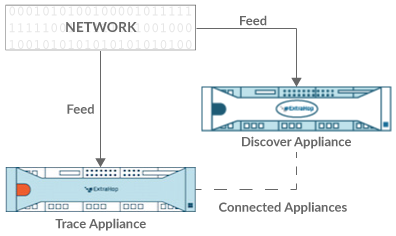
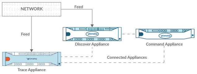
Connect sensors and console to the packetstore
Before you can query for packets, you must connect the console and all sensors to the packetstore.
Connected to a sensor
Connected to sensor and console
Verify the configuration
After you have deployed and configured the packetstore, verify that packets are being collected.
Before you begin
You must have a minimum user privilege of view and download packets to perform this procedure.-
Make sure that the Packets menu appears in the top
menu.

Thank you for your feedback. Can we contact you to ask follow up questions?