Deploy the IDS 8280 sensor
Intrusion Detection System (IDS) sensors integrate with packet sensors to generate detections based on industry-standard IDS signatures. This guide explains how to install the rack-mounted IDS 8280 sensor.
Installation prerequisites
- Sensor
- 1U of rack space and electrical connections for 2 x 750 W power supplies.
- Management
- One 10/100/1000 BASE-T network port for sensor management.
- Monitoring (capture)
- High performance interfaces: One to two network ports for connection to 25 GbE or 10 GbE sources of packet data.
- Management + monitoring interfaces: One to three network ports for connection to 1 GbE sources of packet data.
- Network Access
- Ensure that administrators can access the Administration settings on the sensor over TCP port 443.
For more information about the interfaces on the ExtraHop system, see the ExtraHop Hardware FAQ.
Rear panel ports
EDA 8280
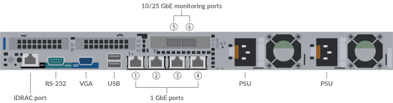
- One iDRAC interface port
- One RS-232 serial port to connect a console device
- One VGA port to connect an external display
- Two USB 3.0 ports to connect input devices such as a keyboard and mouse
- Two power ports to connect the sensor to an AC power source
- Four 10/100/1000 BASE-T network ports. Port 1 is the primary management port. Ports 2 - 4 are the management + monitor ports.
- Two 25 GbE-capable ports on one network adapter. Ports 5 and 6 are the high performance monitoring (capture) interfaces.
Supported packet source connectivity
| IDS 8280 Connector | Peer Connector for Packet Source | Customer-Supplied Cabling | Supported Operating Speeds |
|---|---|---|---|
| Transceiver-based Connectivity | |||
| 25 GbE SFP28 SR transceiver | 25 GbE SFP28 SR transceiver | Multi-mode fiber LC connectors |
25 Gbps, 10 Gbps |
| 10 GbE SFP+ SR transceiver | Multi-mode fiber LC connectors |
10 Gbps | |
| Direct Attach Connectivity | |||
| Customer-supplied SFP28 DAC cable, such as the Mellanox MCP2M00-Axxx series | 25 Gbps | ||
| Customer-supplied RJ45 Ethernet cable | 1 Gbps | ||
Traffic distribution guidelines
- Packets from the same flow should be received on the same interface, or on interfaces of the same network interface card (NIC).
- If your data feed does not require both interfaces on the NIC, disable the unconfigured interfaces in the Administration settings.
- A single high-performance ERSPAN target is expected to process 20 to 30 Gbps. On larger sensors, distribute ERSPAN traffic to more interfaces to scale traffic ingest.
Set up the sensor
-
Connect the power cords.
Connect the two supplied power cords to the power supplies on the back of the sensor, and then plug the cords into a power outlet. If the sensor does not power on automatically, press the power button
 on the front-right of
the sensor.
on the front-right of
the sensor.
Configure the management IP address
DHCP is enabled by default on the ExtraHop system. When you power on the system, interface 1 attempts to acquire an IP address through DHCP. If successful, the IP address appears on the home screen of the LCD.
If your network does not support DHCP, you can configure a static IP address through the LCD menu on the front panel or through the command-line interface (CLI).
| Important: | We strongly recommend configuring a unique hostname. If the IP address on the sensor is changed, the console can re-establish connection easily to the sensor by hostname. |
Configure a static IP address through the LCD
- Make sure that the default management interface is connected to the network and the link status is active.
- Press the select button (✓) to begin.
- Press the down arrow button to select Network, and then press the select button.
- Press the down arrow to select Set static IP, and then press the select button.
- Press the left or right arrows to select the first digit to change, and then press the up or down arrows to change the digit to the desired number. Repeat this step for each digit you need to change. After you configure the desired IP address, press the select button.
- On the Network mask screen, press the left or right arrows to select the first digit to change, and then press the up or down arrows to change the digit to the desired number. Repeat this step for each digit you need to change. After you configure the desired network mask, press the select button.
- On the Default gateway screen, press the left or right arrows to select the first digit to change, and then press the up or down arrows to change the digit to the desired number. Repeat this step for each digit you need to change. After you configure the desired default gateway, press the select button.
- Confirm your modified network settings on the Settings saved screen, and then press any button to return to the Network Menu.
- Press the down arrow and scroll to Set DNS servers, and then press the select button.
- Press the left or right arrows on the DNS1 screen to select the first digit to change, and then press the up or down arrows to change the digit to the desired number. Repeat this step for each digit you need to change, and then press the select button to continue to the DNS2 screen.
- Configure a second DNS server.
- Confirm the DNS settings on the Settings saved screen, and then press any button to return to the Network Menu.
- Press the down arrow twice until ← Back appears, and then press the select button.
- Press the down arrow twice to select iDRAC. Configure the iDRAC DHCP, IP, mask, gateway, and DNS in the same manner as the IP address.
- Press the X button to return to the main menu.
Configure an IP address through the CLI
You can access the CLI by connecting a USB keyboard and SVGA monitor to the appliance or through an RS-232 serial (null modem) cable and a terminal emulator program. Set the terminal emulator to 115200 baud with 8 data bits, no parity, 1 stop bit (8N1), and hardware flow control disabled.
Thank you for your feedback. Can we contact you to ask follow up questions?