Deploy the ExtraHop Explore 5200 Appliance
This guide explains how to install the rack-mounted EXA 5200 ExtraHop Explore appliance.
Installation prerequisites
- Appliance
- 2U of rack space and 2x750W of power
- Management
- One 10/100/1000 BASE-T network port or one 10G BASE-SR port for appliance management.
- Network Access
- TCP port 443 must be open between the Explore appliance and any connected Discover or Command appliances as well as any system that connects to the appliance for administration.
- TCP port 9443 must be open to enable Explore nodes to communicate with other Explore nodes in the same cluster.
For more information about the interfaces on the ExtraHop appliance, see the Appliance Hardware FAQ.
Rear panel ports
EXA 5200
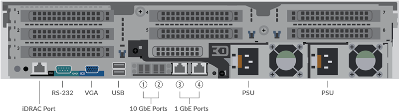
- One iDRAC port
- One RS-232 serial port to connect a console device
- One VGA port to connect an external display
- Two USB 3.0 ports to connect input devices such as a keyboard and mouse
- Two 10 GbE ports. Ports 1 and 2 can be configured as a management port.
- Two 10/100/1000 BASE-T network ports. Port 3 is the primary management port.
- Two power ports to connect the appliance to an AC power source
Set up the appliance
-
Connect the power cords.
Connect the two supplied power cords to the power supplies on the back of the appliance, and then plug the cords into a power outlet. If the appliance does not power on automatically, press the power button
 on the front-right of
the appliance.
on the front-right of
the appliance.
Configure the management IP address
DHCP is enabled by default on the ExtraHop system. When you power on the system, interface 3 attempts to acquire an IP address through DHCP. If successful, the IP address appears on the home screen of the LCD.
If your network does not support DHCP, you can configure a static IP address through the LCD menu on the front panel or through the command-line interface (CLI).
| Important: | For deployments that include a Discover appliance that is connected to a Command appliance, we strongly recommend configuring a unique hostname. If the IP address on the sensor is changed, the Command appliance can re-establish connection easily to the sensor by hostname. |
Configure a static IP address through the LCD
Configure an IP address through the CLI
You can access the CLI by connecting a USB keyboard and SVGA monitor to the system or through an RS-232 serial cable and a terminal-emulator program. The terminal emulator must be set to 115200 bps with 8 data bits, no parity, 1 stop bit (8N1), and hardware flow control should be disabled.
(Optional) Configure the 10 GbE management interface
You can configure a 10 GbE port (port 1 or port 2) to manage the system. The commands below move the settings from port 3 to port 1 and then disables port 3. Alternatively, you can configure the 10 GbE management interface in the Administration settings.
Create an Explore cluster
For the best performance, data redundancy, and stability, you must configure at least three Explore appliances in an Explore cluster.
| Important: | If you are creating an Explore cluster with six or more nodes, you must configure the cluster with manager nodes. For manager node instructions, see Deploying manager nodes. |
In the following example, the Explore appliances have the following IP addresses:
- Node 1: 10.20.227.177
- Node 2: 10.20.227.178
- Node 3: 10.20.227.179
You will join nodes 2 and 3 to node 1 to create the Explore cluster. All three nodes are data nodes. You cannot join a data node to a manager node or join a manager node to a data node to create a cluster.
| Important: | Each node that you join must have the same configuration (physical or virtual) and the same ExtraHop firmware version. EXA 5100 and EXA 5200 physical appliances can be in the same cluster. |
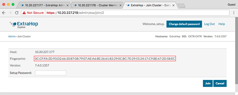
Before you begin
You must have already installed or provisioned the Explore appliances in your environment before proceeding.-
Confirm that the fingerprint on this page matches the fingerprint you noted in
step 3.
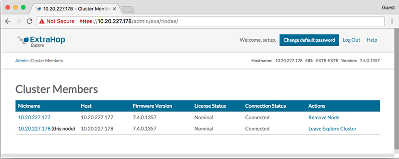
-
Click Cluster Members. You should see node 1 and node 2 in
the list.
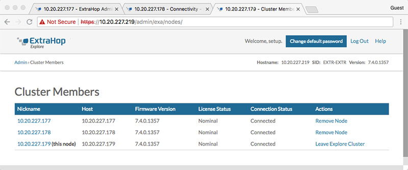
-
When you have added all of your Explore appliances to the cluster, click
Cluster Members in the Explore
Cluster Settings section. You should see all of the joined nodes
in the list, similar to the following figure.
Configure the Explore appliance
After you configure an IP address for the Explore appliance, log in to the Administration settings on the ExtraHop system through https://<extrahop-hostname-or-IP-address>/admin, and complete the following recommended procedures.
| Note: | The default login username is setup and the password is the system serial number, which can be found on a sticker on the rear of the chassis. Alternatively, the serial number appears in the Info section of the LCD display. |
- Register your ExtraHop system
- Connect the Discover and Command appliances to Explore appliances
- Send record data to the Explore appliance
- Review the Explore Post-deployment Checklist and configure additional Explore appliance settings.
Thank you for your feedback. Can we contact you to ask follow up questions?