Deploy an ExtraHop sensor on Google Cloud Platform
The following procedures explain how to deploy a virtual ExtraHop packet sensor in a Google Cloud environment. You must have experience deploying virtual machines in Google Cloud within your virtual network infrastructure.
An ExtraHop virtual sensor can help you to monitor the performance of your applications across internal networks, the public internet, or a virtual desktop interface (VDI), including database and storage tiers. The ExtraHop system can monitor application performance across geographically distributed environments, such as branch offices or virtualized environments through inter-VM traffic.
This installation enables you to run network performance monitoring, network detection and response, and intrusion detection on a single sensor.
| Important: | The IDS module requires the NDR module. Before you can enable the IDS module on this sensor, you must upgrade the sensor firmware to version 9.6 or later. When the upgrade completes, you can apply the new license to the sensor. |
| Note: | If you have enabled the IDS module on this sensor, and your ExtraHop system does not have direct access to the Internet and access to ExtraHop Cloud Services, you will need to upload IDS rules manually. For more information, see Upload IDS rules to the ExtraHop system through the REST API. |
To ensure that the deployment is successful, make sure you have the ability to create the required resources. You might need to work with other experts in your organization to ensure that the necessary resources are available.
System requirements
Your environment must meet the following requirements to deploy a virtual ExtraHop sensor in GCP:
- You must have a Google Cloud Platform (GCP) account.
- You must have the ExtraHop deployment file, which is available on the ExtraHop Customer Portal.
- You must have an ExtraHop sensor product key.
- You must have packet mirroring enabled in GCP to forward network traffic to the ExtraHop
system. Packet mirroring must be configured to send traffic to nic1 (not nic0) of the
ExtraHop instance. For more information, see https://cloud.google.com/vpc/docs/using-packet-mirroring.
Important: To ensure the best performance for initial device synchronization, connect all sensors to the console and then configure network traffic forwarding to the sensors. - You must have firewall rules configured to allow DNS, HTTP, HTTPS, and SSH traffic for ExtraHop administration. For more information, see https://cloud.google.com/vpc/docs/using-firewalls.
Virtual machine requirements
You must provision a GCP instance type that most closely matches the virtual sensor size and meets the following module requirements.
| Sensor | Modules | Machine type | Boot disk type | Boot disk size | Datastore disk type | Datastore disk size |
|---|---|---|---|---|---|---|
| RevealX Ultra 1 Gbps | NDR, NPM, Packet Forensics | n1-standard-8 (8 vCPUs, 30 GB memory) | NA | NA | Balanced persistent disk | 150 GiB |
| RevealX Ultra 10 Gbps | NDR, NPM, Packet Forensics | n2-standard-32 (32 vCPUs, 128 GB memory) | NA | NA | Balanced persistent disk | 1000 GiB |
| EDA 1100v | NDR, NPM | n1-standard-4 (4 vCPUs and 15 GB memory) | NA | NA | Standard persistent disk | 61 GiB |
| EDA 6320v | NDR, NPM, IDS | n2-standard-32 (32 vCPUs and 128 GB memory) | NA | NA | Balanced persistent disk | 1400 GiB |
| EDA 8370v 20 Gbps | NDR, NPM, IDS, Packet Forensics | n2-standard-80 (80 vCPUs, 320 GB memory) | Standard persistent disk | 10 GiB | Balanced persistent disk | 3000 GiB |
| Note: | Throughput might be affected when more than one module is enabled on the sensor. |
Packetstore disk requirements
You must configure a packetstore disk for all RevealX Ultra sensors. For EDA 8370v sensors, you must configure packetstore disks only if the Packet Forensics module is enabled.
| Sensor | Disk type | Disk size (for each disk) | Number of disks | Provisioned throughput |
|---|---|---|---|---|
| RevealX Ultra 1 Gbps | Standard persistent disk | 4000 GiB | 1 | NA |
| RevealX Ultra 10 Gbps | Balanced persistent disk | 32000 GiB | 1 | NA |
| EDA 8370v 20 Gbps | Hyperdisk Throughput Hyperdisk Throughput is not available in all GCP regions and zones. For more information, see the GCP documentation site. |
13000 GiB | 5 | 600 MiB/s |
| Note: | You must distribute storage equally across all packetstore disks. |
Upload the ExtraHop deployment file
Next steps
When the file upload completes, you can create the image.Create the image
- From the navigation menu, click .
- Click Create Image.
- In the Name field, type a name to identify the ExtraHop sensor.
- From the Source drop-down menu, select Cloud Storage file.
- In the Cloud Storage file section, click Browse, locate the extrahop-<module>-gcp-<version>.tar.gz file in your storage bucket and then click Select.
- Configure any additional fields that are required for your environment.
- (Optional):
For 10G sensors (such as the Ultra 10G, EDA 6320v, and EDA 8370v), complete the
following steps.
- Click Create to complete the image creation.
Create the packetstore disk
| Note: | A packetstore disk is required only for RevealX Ultra 1 Gbps, RevealX Ultra 10 Gbps, and EDA 8370v sensors. |
Create the VM instance
-
In the Network tags field, type the following tag names:
- https-server
- http-server
- dns
- ssh-all
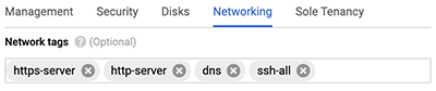
Important: Network tags are required to apply firewall rules to the ExtraHop instance. If you do not have existing firewall rules that allow this traffic, you must create the rules. For more information, see https://cloud.google.com/vpc/docs/using-firewalls.
Create an instance group
- In the left pane on the Compute Engine page, click Instance groups.
- Click Create Instance Group.
- Click New unmanaged instance group.
- In the Name field, type an instance group name.
- From the Network drop-down menu, select the network that the instance can access.
- From the Subnet drop-down menu, select your network subnet.
- From the Select VM drop-down menu, select your sensor.
- Click Create.
Create a traffic mirroring policy
- From the navigation menu, click .
- Click Create Policy.
- In the Policy name field, type a new policy name.
- From the Region drop-down menu, select your geographic region.
- Click Continue.
- Select Mirrored source and collector destination are in the same VPC network.
- From the Network drop-down menu, select the VPC network.
- Click Continue.
- Select the Select one or more subnetworks checkbox.
- From the Select subnet drop-down menu, select the checkbox next to your subnet.
- Click Continue.
- Select the checkbox next to the VM instance.
- Click Continue.
- From the Collector destination drop-down menu. select the load balancer that you previously created.
- Click Continue.
- Select Mirror all traffic (default).
- Click Submit.
Configure the sensor
Before you begin
Before you can configure the sensor, you must have already configured a management IP address.Next steps
After the system is licensed, and you have verified that traffic is detected, complete the recommended procedures in the post-deployment checklist.
Thank you for your feedback. Can we contact you to ask follow up questions?