Deploy the EDA 6370 sensor
This guide explains how to install the rack-mounted EDA 6370 sensor. The EDA 6370 is a physical sensor that delivers NDR, NPM, IDS, and ETA without additional sensors.
During installation, you will configure the sensor with one of the following options
- Packet sensor
-
This installation enables you to run network performance monitoring, network detection and response, and intrusion detection on a single sensor. By adding the IDS module, you can also upload and view IDS detections.
-
Important: The IDS module requires the NDR module. Before you can enable the IDS module on this sensor, you must upgrade the sensor firmware to version 9.9 or later. When the upgrade completes, you can apply the new license to the sensor. Note: If you have enabled the IDS module on this sensor, and your ExtraHop system does not have direct access to the Internet and access to ExtraHop Cloud Services, you must to upload IDS rules manually. For more information, see Upload IDS rules to the ExtraHop system through the REST API.
- IDS sensor
- Intrusion Detection System (IDS) sensors integrate with packet sensors to generate detections based on industry-standard IDS signatures.
- Packet Forensics
- Packet Forensics requires installation of one or more ExtraHop Extended Storage Units (ESU).
Installation prerequisites
- Sensor
- 1U of rack space and electrical connections for 2 x 800W power supply units (PSUs).
- Management
- One 10/100/1000 BASE-T network port for sensor management.
- Monitoring (capture)
- High performance interfaces: One to two network ports for connection to 25 GbE or 10 GbE sources of packet data.
- Management + monitoring interfaces: One to three network ports for connection to 1 GbE sources of packet data.
- Network Access
- Ensure that administrators can access the Administration settings on the sensor over TCP port 443.
- Configure your firewall rules to allow outbound access over port 443 to ExtraHop Cloud Services.
- For a list of default port specifications, see the Default Port Specifications Reference .
For more information about the interfaces on the ExtraHop system, see the ExtraHop Hardware FAQ.
Rear panel ports
EDA 6370
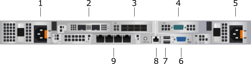
- Power supply unit (PSU1) to connect the sensor to an AC power source
- Two 25 GbE-capable ports on two network adapters that can be configured as high-performance monitoring (capture) interfaces or high-performance ERSPAN/VXLAN/GENEVE targets
- Four SAS ports to connect extended storage units (ESU) when enabling Packet Forensics
- One RS-232 serial port to connect a console device
- Power supply unit (PSU2) to connect the sensor to an AC power source
- One VGA port to connect an external display
- Two USB 3.0 ports to connect input devices such as a keyboard and mouse
- One iDRAC interface port
- Four 10/100/1000 BASE-T network ports where ports 1 and 2 can be configured as a management
port or a management and RPCAP/ERSPAN/VXLAN/GENEVE target
Tip: In environments with asymmetric routing adjacent to the high-performance interfaces, ping replies might not be returned to the sender.
Supported packet source connectivity
The sensor accepts packets through ports 1 to 6. Connect the ports according to the table below.
| Connector | Peer Connector for Packet Source | Customer-Supplied Cabling | Supported Operating Speeds |
|---|---|---|---|
| 10 GbE SFP+ SR transceiver | 10 GbE SFP+ SR transceiver | Multi-mode fiber LC connectors |
10 Gbps |
Direct Attach Connectivity
| Cable Type | Supported Operating Speeds |
|---|---|
| Customer-supplied SFP28 DAC cable, such as the Mellanox MCP2M00-Axxx series | 10 Gbps |
| Customer-supplied RJ45 Ethernet cable | 1 Gbps |
| Note: | The packet processing capability of the sensor is 10 Gbps. While it is possible to oversubscribe the sensor by sending more than 10 Gbps of packet data across the two 10 GbE-capable ports and four 1 GbE-capable ports, inbound workloads that exceed 10 Gbps will result in dropped packets. |
Set up the sensor
-
Connect the power cords.
Connect the two supplied power cords to the power supply units (PSUs) on the back of the sensor, and then plug the cords into a power outlet. If the sensor does not power on automatically, press the power button
 on the front-right of the sensor.
Note: Monitoring interfaces are enabled after a license is activated on the ExtraHop appliance.
Management IP address configuration
DHCP is enabled by default on the ExtraHop system. When you power on the system, the primary management interface attempts to acquire an IP address through DHCP. If successful, the IP address appears on the home screen of the LCD.
If your network does not support DHCP, you can configure a static IP address through the LCD menu on the front panel or through the command-line interface (CLI).
| Important: | We strongly recommend configuring a unique hostname. If the system IP address changes, the ExtraHop console can re-establish connection easily to the system by hostname. |
Configure a static IP address through the LCD
Configure an IP address through the CLI
Before you begin
You can access the CLI by connecting a USB keyboard and SVGA monitor to the appliance or through an RS-232 serial (null modem) cable and a terminal emulator program. Set the terminal emulator to 115200 baud with 8 data bits, no parity, 1 stop bit (8N1), and hardware flow control disabled.You can manually configure an IP address from the CLI.
Configure the sensor
Before you begin
Before you can configure the sensor, you must have already configured a management IP address.Next steps
After the system is licensed, and you have verified that traffic is detected, complete the procedures in the post-deployment checklist.
Thank you for your feedback. Can we contact you to ask follow up questions?